Conditioning NOS GU74b Tubes in
your ACOM-1000 Amplifier
Important Disclaimer - This worked for me. It may NOT work for you. It is not published anywhere else or recommended by ACOM. There was no clear documentation that I could find anywhere on the Internet, or anything from ACOM or any other manufacturer of amplifiers designed around 4CX800A/GU74b tubes. There were lots of conflicting opinions on the use of NOS tubes. IF YOU FOLLOW THESE INSTRUCTIONS, YOU ARE ON YOUR OWN. Just because it worked for me DOES NOT MEAN IT WILL WORK FOR YOU! You run the risk of SERIOUS INJURY AND EVEN DEATH because you will be dealing with LETHAL VOLTAGES AS HIGH AS 3000 VOLTS. You run the risk of DAMAGING YOUR AMPLIFIER. I highly suspect this will also VOID YOUR WARRANTY FROM ACOM. Read everything here carefully and PROCEED AT YOUR OWN RISK. If you are not used to working on amplifiers or are inexperienced with high voltages, STOP NOW AND RETURN THE AMPLIFIER TO ACOM TO HAVE THIS PROCEDURE PERFORMED, OR HIRE A TRAINED ELECTRONICS TECHNICIAN FAMILIAR WITH HIGH POWER TRANSMITTING TUBES AND AMPLIFIERS.
Two NOS GU74b EX:Soviet Union military tubes were conditioned as described below. One was manufactured in June, 1987, the other in February 1988. Both tubes appeared to be in like new shape, and they were in their original sealed packages with an insert containing instructions in the Cyrillic alphabet that I could not understand. This is what I did:
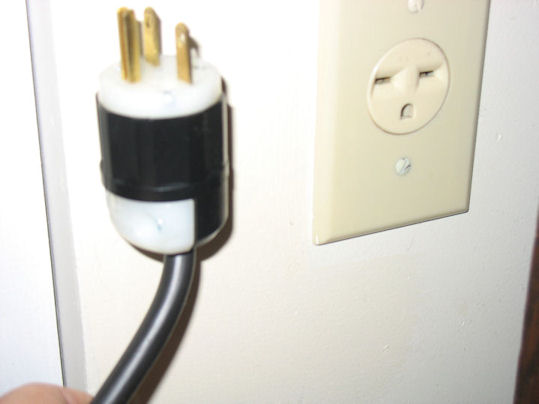
(1) Unplug the amplifier from the wall and, and turn the main switch on the rear of the amplifier OFF:
(2) Wait 30 minutes and
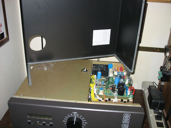
then remove the 9 Phillips screws to release the top cover, and lift it off.
Do not touch anything yet. Before proceeding, you must make
sure that no residual DANGEROUS VOLTAGES are present in the amplifier. The
best way to do this is to make a well insulated wire (a shorting wire) about 3-4
feet long (capable of handling 3000 Volts) and strip about 1/2 inch off of both
ends. Fasten one end of the wire under the GROUND STUD on the rear panel.
Then, holding the shorting wire by the insulation, back about 4 inches from the
bare part, touch the stripped end for 1-2 seconds on all parts on the HV
rectifier PCB, especially:
- the HV output J3;
- the wire-wound resistor R12 on its both sides;
- the four HV diodes on their both sides.
With the same shorting wire, on the MAINS PCB touch diode D19
on both sides (it is located at the PCB edge, near the power transistor that is
installed on the chassis.)
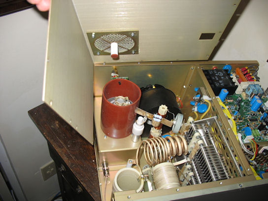
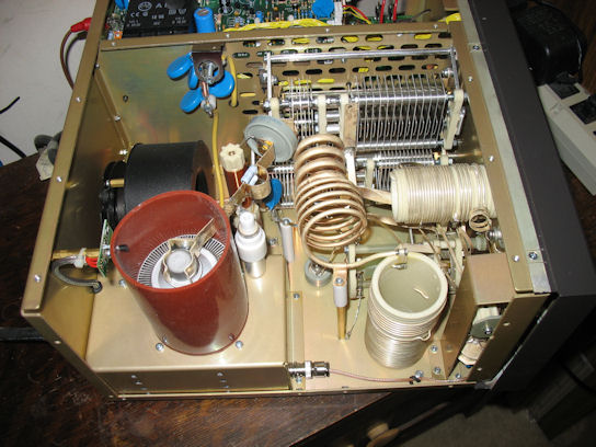
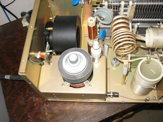
(3) Remove the 15 countersunk-head
screws and release the aluminum cover (RF screen) above the RF deck. Lift and
pull the cover to remove it, exposing the RF deck and allowing access to the
tube. Use the shorting wire described above and touch the copper strip of
the plate anti-parasitic suppressors and the tube anode. Make 100% sure
the HV LID crowbar makes a reliable short-circuit across the HV wiring when the
cover is off.
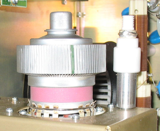
(4) Remove the Philips screw from the plate capacitive divider (this is the aluminum / Teflon cylinder installed near the tube, on the tube deck):
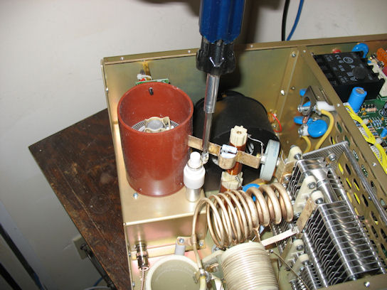
(5) Remove the brass hexagon-head bolt from the ceramic DC-blocking capacitor (near the plate choke):
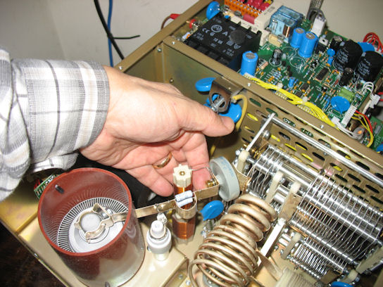
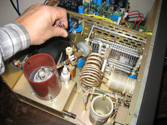
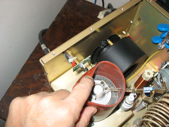
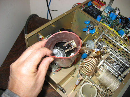
(6) Remove the tube chimney. First carefully push the temperature sensor (that looks like a small transistor) out through the side, being careful not to bend the leads. Unclip the anode spring clip from tube cap, and while pressing down on the tube cap, work the the rubber chimney up off of the tube, together with the anti-parasitic suppressor and copper strip.
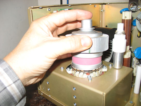
(7) Pull the tube straight up, being very careful not to bend it sideways as this may may destroy tube socket.
![]()
(8) Insert the NOS GU74b tube to be conditioned into the socket, again being careful to insert it straight down with the pins properly aligned. Make sure that all 16 of the socket's spring contacts are outside the tube, and clipped tightly against the tube screen-grid ring.
(9) Replace the tube chimney and the plate capacitive divider in the reverse order as described above in steps (4), (5) and (6.) Then replace the RF cover (a/k/a RF Screen) and secure it in place with the 15 Phillips screws. You may have to adjust the idling (zero-signal) plate current of the tubes for low- and high- RF-drive levels. In order to determine if this is necessary, the amplifier must be powered on. DO NOT PROCEED WITH THIS STEP UNLESS YOU ARE ABSOLUTELY SURE YOU KNOW WHAT YOU ARE DOING AND QUALIFIED TO WORK WITH VOLTAGES AROUND 3000V. As mentioned in the disclaimer at the top of the page, these are lethal voltages and it is better to send the amp back to the factory than to risk your life.
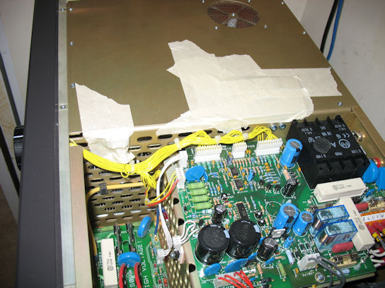
First, you have to defeat the crowbar and "cover presence" interlock. I used a plastic plate and masking tape. This is so you can work on the bias voltage adjustments for the idling currents with the power on. These adjustments are two small trimmer potentiometers in the MAINS PCB labeled RP1 and RP2.
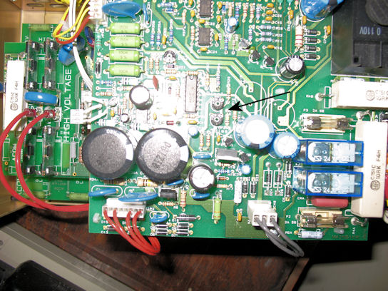
(10) There is a document floating around the Internet that I believe came from ACOM entitled "ACOM1000 TUBE REPLACEMENT INSTRUCTION.doc" that describes in detail how to set the idling plate currents. Both NOS tubes I conditioned exhibited characteristics that allowed the idling currents to fall within ACOM's recommended tolerances of 60-80mA and 200-240mA. If this is not the case, you probably should adjust RP1 and RP2 as described in the aforementioned document. I will not go into it here because it falls outside the scope of these instructions; is available elsewhere, and since I did not have to do it, I am unable to confirm that the documentation I found is correct.
Now the interesting part! Assuming everything has been reassembled correctly, it is time to power on the amplifier with the NOS tube. Since there is no way to know what the idling plate currents will be without power, this step has to be done with the main cover off and the interlocks defeated as shown above. Plug the amp into the wall socket and turn on the main power rocker switch at the rear. The amp should display "ACOM-1000" in the front LCD display. If it doesn't, something is wrong, and I can't help you. Call your ACOM dealer! Assuming you have the proper display, after 30-60 seconds press the red ON/OFF button on the front. The amp should power up as usual and begin the 150-second warm-up countdown. If it doesn't, I can't help you. Call your ACOM dealer! Once it goes through the warm-up, you will get the usual LCD display. Toggle through the screens and ensure that things look normal. In particular the plate voltage should be 2600-2650 and the idling plate currents should be within 60-80mA and 200-240mA. If so, you can either power it down, remove the interlock defeating tape (or however you did it) and put the main cover back on. This is the safest way, but since I had two tubes to condition plus putting the original tube back in, I decided to do everything with the cover off. If you choose this route, MAKE 100% SURE YOU NEVER LEAVE THE AMP UNATTENDED; SOMEONE MAY WANDER BY AND TOUCH IT!
Either way, now is when you begin "conditioning" the tubes. How? That's easy. You wait. Let the amp sit powered on in idle mode for 4-5 hours. I left it 5 hours per tube. Maybe 3 is enough, and maybe 7-8 would be better. The idea is to allow the getter to de-gas the tube. Based on what I could find out, most "experts" recommend ramping up both the heater current and the plate voltage incrementally over a 4-5 hour period. This requires (all external to the amp) a variable current source for the filament, a fan with the proper capacity to keep the tube cool, and some sort of variable high voltage power supply that will go from 500 volts to 2700 volts in 300-500 volt increments. You would also need a tube socket and a spare chimney. Since I am not an Electrical Engineer, I don't have this sort of equipment laying around, nor do I know where to get it. That's why I used the amplifier to condition the tubes!
After 5 hours, I switched the amplifier to operate mode and let it sit for another 5-10 minutes. Then I tuned it up for 400 watts out on 20-metres. I was careful to note the TUNE and LOAD settings, and in both cases I found them to be the same as they had been with the original tube. I then called CQ and had a 10-15 minute chat. This was to exercise the tube at less than half its capacity. I next doubled the power to 800 watts and repeated the 10-15 minutes of usage. While doing this I cycled through the various menus and noted the readings were almost the same as they had been with the original tube. Finally I went to 40-metres and tuned the amp for full power - 1200 watts and called CQ on CW several times, probably transmitting for several minutes. Again I monitored the various parameters and found everything to be close to those observed with the original tube.
Finally, replace the tube that was conditioned with the original tube, making sure to unplug the amp and wait 30 minutes before touching anything.
At this point I considered the tubes thoroughly "conditioned" and exercised, and fault free. Should the original tube fail, I would not hesitate to replace it with one of them. This would be a 20-30 minute job. I believe this "conditioning" procedure, although not without risk to your amp if a tube were shorted or arced due to age, to be the best the average Amateur can perform. To be 100% sure, one would have to convince ACOM to do it for you, or to sell you a pre-conditioned tube. As of this writing (30 January 2008), I cannot find any amplifier or tube vendor that stocks new or "conditioned" NOS 4CX800As or GU74b tubes. Hopefully this will change in the future.
Last updated on 13 December 2020